I figure that the right wing, now under construction, is unsurprisingly similar to the left, and therefore would be boring in the extreme if I were to chronicle that in detail. So I'll resist the urge and and rather just give you general updates so you can see where I'm up to.
Today was a rare opportunity to spend most of the day in the ACF. I finished riveting the bottom skins in place and with the help of the Minister for Family Affairs flipped the beast over. I am now at the stage where the bottom skin are wrapped around the nose and riveted in place. In the next step the final three top skins need to be prepared and riveted in place.
There are other stories to be told from the wonderful world of aircraft construction/flying during the period of blogging vacuum, but I'll save them for another day.
RV-12 - A Builder's Journey
An account of a voyage into uncharted waters of airplane construction
Saturday, January 7, 2012
End of a Long (Posting) Break
The fault is entirely that of a lazy blogger, you know you get behind a few times, it seems harder to catch up, you put it off, it gets harder to catch up.............and so it goes!
So here we are in the New Year with a firm resolution to do better. Progress with the build in the last few months can only be described as intermittent. At the last report the tailcone was almost complete. I'm pleased to say that is finished and in storage. The left wing skins are in place and is securely stored in the wing stand expertly constructed according to the plans used by many builders. The right wing is well under way and I am currently engaged in riveting the bottom skins. This series of photos will summarises progress over the last 4 months. Slow eh!
This is the forward skin rib it is riveted on the top of the tailcone and will be the forward fixing for the vertical stabilizer (tail fin).
Here it is riveted in place.
I prepared and fixed the fiberglass fairings at the top of the vertical stabilizer and rudder.
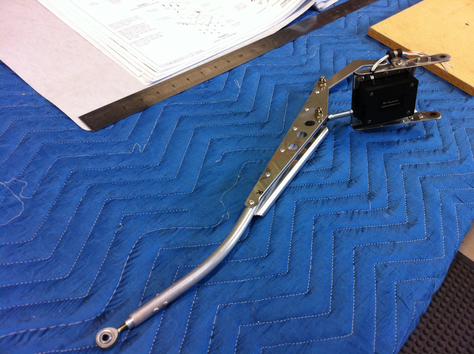
I assembled the trim motor and actuator assembly. It gets fitted to the rear bulkhead later in the build.
The completed tail-cone is gathering dust in the shed.
Tapping a thread that will receive an eye bolt which is a aircraft tie-down point.
Brackets attached to the main wing spar to which the ribs are attached.
The top piece below is a doubler which strengthens the rear spar (bottom of the picture) at the inboard end.
Clecoed in place ready for riveting.
All done.
These are flaperon attach brackets. The flaperons attach to the rear of the wings.
This is the inboard attach bracket complete with bearing.
The attach brackets temporarily fitted to main wing ribs.
A pile of main wing ribs. There are dozens and dozens of these. They require hours and hours of mind-numbingly tedious deburring and fluting to straighten them. It was a huge relief to be finished this let me tell you.
Here are a couple clecoed in place ready to be riveted to the mains spar attach brackets.
The main wing ribs all attached to the main spar, every builder takes this photo looking though the main ribs the whole length of the wing.
This is the assembled stall warning mechanism. It is attached to a nose rib in the left wing. The stainless steel flat at the front of this photo protrudes from the front of the wing and activates the micro-switch which in turn sounds a warning when the aircraft is approaching a stall.
This is the left wing ready for the skins to be attached. The rear spar is in the foregound.
This is the assembly that affixes to the inboard wing rib and will allow electrical connection between the wing and fuselage for lights and the staff warning.
Now in place. The strings run the lenth of the wing and will later be used to pull wires for the lights.
The outboard skin, left wing ready to be riveted.
The inboard left skin riveted in place.
Here the nose ribs are close together at the inboard end of the wing. They are close because this is where you step up onto the wing to get into the aircraft.
The left wing, bottom skin is complete and almost ready to be turned. The skins will wrap around the leading edge of the wing, they are hanging down at the front of the photo.
There is an access point in the bottom of the wing adjacent to the stall warning mechanism. You can see it in the photos above and below.
The top skins are now riveted to the left wing and the wing walk doubler is about to riveted on top at the inboard end This adds a second layer of skin for strength where you step into the aircraft.
The wings on the RV-12 are removable. This is the hand-hold hole at the outboard end of the left wing
The left top outboard skin is partially complete as shown here. I have not completed the wing tip because (a) I a waiting for the lighting kit and (b) I'm not satisfied with the workmanship and need a replacement part to do a better job.
The left wing is about 95% complete and safe and sound in the wing stand.
Thursday, August 11, 2011
About to Wing it
It seems like a long time since the last post - and it is. There is some progress to report but I have to say that the paying job and other activities continue to have an adverse impact on activity in the ACF.
The tailcone is all but complete. I finished riveting the skins in place and prepared and riveted the Forward Skin Rib to the tops skin.
Here is the completed fuselage cone.
I have decided to deviate from the order of build as have many others and delay the attachment of the empennage to the tailcone as is called out in the order of build. This is due in the main to the lack of storage space for the tailcone plus empennage. I did have a dip into Section 11 (Empennage Attachment) though in order to attach the fibreglass fairings to the rudder and to the vertical stabilizer assemblies. This proved to be relatively easy with some trimming of the fibreglass accomplished with the aid of the trusty Dremel tool with cutting disk and sandpaper over both rectangular and round configuration sanding blocks. Here they are cleoced in place and test fitted ready for riveting.
After riveting these in place I decided to attack the construction of the Pushrod Assembly. This involves a 12 volt servo unit attached to a rod which when finally installed will connect with the anti-servo tabs and provide elevator trim capability in fight by adjusting elevator control pressure. It gets installed at the same time as the empennage, now a way down the track. The servo unit wiring is also connected to the wiring that is currently protruding from the rear of the tailcone. I would have installed the connectors to the wiring on both, but I need to acquire a much better crimping tool. It's incredible how this plane building provides the perfect excuse to populate the tool kit with new and better goodies.
Oh yes, and the (later) fitting of the pushrod assembly requires among other things the fabrication of a couple of spacers carefully cut from the provided 5/16 aluminum tubing. This makes perfect sense, save that I don't have sufficient aluminum tubing left as a consequence of a miss-cut in an earlier process. I feel an order from Oregon coming on. I'm thinking about what else I need to order to minimise the pain of heavy freight cost for a part that weighs about the same as a couple of ball-point pens.
Onwards and upwards, its time start on the wings or specifically one wing as I don't have space to build them both at the same time, which I'm sure in an ideal world would make a whole lot of sense. I spent a happy hour or two sorting the hardware - nuts, bolts, rivets etc. etc. into labelled bins so that they are easily found when needed. This instead of sorting throgh numerous of the ubiquitous Vans paper bags.I then proceeded to unload the parts stored in the crate in which they arrived, and stacked them in sub-kits in shelving adjacent to the construction table. The skins stay in the crate, safe and sound until needed.
I started at the beginning - that would be Step 1 in the plans that requires the separation of some attach angles. I deburred the edges and holes in these, and that folks is the sum of progress to date.
Labels:
Empennage,
Page 10-10,
Page 11-05,
Page 11-06,
Page 11-07,
Page 12-02,
Page 12-03,
Page 12-04,
Page 13-01,
Page 13-02,
Wings
Wednesday, July 27, 2011
Better late.....................
It's overtime for an update. Friends, no posting does not mean no action. I have excuses, but will keep those to myself. this post will update a few (part) days of building. It chronicles a fair part of the assembly of the tailcone. The final preparatory part of the rear bulkhead assembly was to attach the bushing and hinge brackets called out in this section of the plans
This is followed by test fitting the rear bulkhead to the stabilator assembly incorporating selection of the appropriate washers to ensuire a good fit. This was completed with only a minor wrestle of the tiny washers into place, assisted by the judicious application of super glue to hold said washers where they should be.
The preparatory work now complete, attention now turns to the assembly of the tailcone. It could just be that this will herald the first identification of the project as something approaching the look of an aircraft part. We shall see. This is the laying out of the first of the skins (bottom - the assembly is upside down at this point).
You can see here the three tailcone ribs attached to the bottom skins with the left bottom skin clecoed in place.
Here with the bottom and left and right bottom skins riveted in place.
Paul turned up at this point and helped with the clecoing and riveting of the side skins. The whole assembly was turned the right way up and some strings run to assist the later installation of the control cables, very difficult once the tailcone is closed up, unless the strings are available to pull them through.
Here the novice master builder is running and affixing wires that control the trim mechanism
As shown here the wire protrudes the required distance from the rear bulkhead assembly (now clecoed in place), later to be connected to the motorised trim mechanism
I thought this looked like an outstandingly good (and simple) effort. Later that evening I was browsing the Vans forum and discovered that other builders have provided advice that there is a right and wrong way to install this wire, the connector pins need to be at the front end. Strangely the otherwise comprehensive building plans are silent on this point. With a 50/50 chance of stuffing this up, I repaired to the shed and cautiously removed the tape evident on the end of the wires shown above. Sure enough - pins! I'm going to need to remove a number of cable ties and reverse the wire. Fortunately I have yet to put the top skins in place so I have access to do this. No drama.
So this is the current state of play. The affixing of the top skin, a stiffener and the fixing plate as shown below will complete the tailcone section of the build.

I think it's progressing well given the competing demands for construction time and given that construction only began on May 26th. This is fun - and very satisfying.
This is followed by test fitting the rear bulkhead to the stabilator assembly incorporating selection of the appropriate washers to ensuire a good fit. This was completed with only a minor wrestle of the tiny washers into place, assisted by the judicious application of super glue to hold said washers where they should be.
The preparatory work now complete, attention now turns to the assembly of the tailcone. It could just be that this will herald the first identification of the project as something approaching the look of an aircraft part. We shall see. This is the laying out of the first of the skins (bottom - the assembly is upside down at this point).
You can see here the three tailcone ribs attached to the bottom skins with the left bottom skin clecoed in place.
Here with the bottom and left and right bottom skins riveted in place.
Paul turned up at this point and helped with the clecoing and riveting of the side skins. The whole assembly was turned the right way up and some strings run to assist the later installation of the control cables, very difficult once the tailcone is closed up, unless the strings are available to pull them through.
Here the novice master builder is running and affixing wires that control the trim mechanism
As shown here the wire protrudes the required distance from the rear bulkhead assembly (now clecoed in place), later to be connected to the motorised trim mechanism
I thought this looked like an outstandingly good (and simple) effort. Later that evening I was browsing the Vans forum and discovered that other builders have provided advice that there is a right and wrong way to install this wire, the connector pins need to be at the front end. Strangely the otherwise comprehensive building plans are silent on this point. With a 50/50 chance of stuffing this up, I repaired to the shed and cautiously removed the tape evident on the end of the wires shown above. Sure enough - pins! I'm going to need to remove a number of cable ties and reverse the wire. Fortunately I have yet to put the top skins in place so I have access to do this. No drama.
Blissfully ignorant of this at the time, Paul and I pressed ahead with the clecoing and riveting. It was great to have help with this, it's amazing how quickly it goes with two on the job.
So this is the current state of play. The affixing of the top skin, a stiffener and the fixing plate as shown below will complete the tailcone section of the build.
I think it's progressing well given the competing demands for construction time and given that construction only began on May 26th. This is fun - and very satisfying.
Labels:
Empennage,
Page 10-04,
Page 10-05,
Page 10-06,
Page 10-07,
Page 10-08,
Page 10-09
Subscribe to:
Posts (Atom)